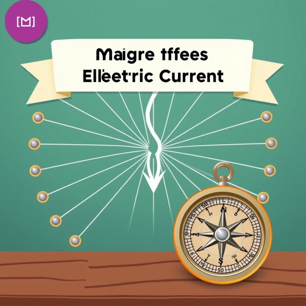
MP Board Class 10 Science Chapter 12: Magnetic Effects of
Chapter 12: Magnetic Effects of Electric Current — This chapter explores the fascinating relationship between electricity and magnetism. You will learn about magnetic fields produced by current-carrying conductors, the force on a current-carrying conductor in a magnetic field, electromagnetic induction, and practical applications like electric motors and generators. In the MP Board Class 10 Science exam, this chapter carries approximately 6-8 marks, making it crucial for board preparation.
📑 Table of Contents
🧲 1. Magnetic Field and Field Lines
A magnetic field is the region around a magnet where its magnetic influence can be felt. The concept was first systematically studied by Hans Christian Oersted in 1820, who discovered that a current-carrying wire deflects a compass needle, establishing the fundamental link between electricity and magnetism.
Properties of Magnetic Field Lines
- Magnetic field lines are closed continuous curves — they emerge from the north pole and enter the south pole outside the magnet, and travel from south to north inside the magnet.
- Field lines never intersect each other. If they did, it would imply two directions of the magnetic field at the same point, which is impossible.
- The tangent at any point on a field line gives the direction of the magnetic field at that point.
- The closeness or density of field lines indicates the strength of the magnetic field — closer lines mean a stronger field.
- The relative strength of a magnetic field is maximum near the poles where field lines are most concentrated.
Earth’s Magnetic Field
The Earth behaves like a giant bar magnet with its magnetic south pole near the geographic north pole. A freely suspended magnet always aligns itself in the north-south direction due to the Earth’s magnetic field. The strength of the Earth’s magnetic field is about 0.3 to 0.5 Gauss. Interestingly, the Earth’s magnetic poles have reversed many times throughout geological history — a phenomenon recorded in magnetic minerals in ancient rocks.
⚡ 2. Magnetic Field Due to a Current-Carrying Conductor
Oersted’s experiment demonstrated that an electric current produces a magnetic field around it. When a current flows through a conductor, it creates a circular magnetic field around it. The direction of this magnetic field depends on the direction of the current. This discovery laid the foundation for electromagnetism and all modern electrical devices.
Right-Hand Thumb Rule
The direction of the magnetic field around a straight current-carrying conductor can be determined using Maxwell’s Right-Hand Thumb Rule: If you hold the conductor in your right hand with your thumb pointing in the direction of the current, then your curled fingers indicate the direction of the magnetic field lines.
📘 Key Concept: The magnetic field pattern around a straight conductor consists of concentric circles centered on the conductor. The field strength is inversely proportional to the distance from the conductor — the farther you go, the weaker the field.
Magnetic Field of a Solenoid
A solenoid is a coil of many circular turns of insulated copper wire wrapped closely in the shape of a cylinder. When current passes through it, the magnetic field inside the solenoid becomes uniform and parallel to its axis. The field outside the solenoid is very weak. A solenoid behaves like a bar magnet with one end acting as the north pole and the other as the south pole.
Electromagnet
An electromagnet consists of a soft iron core placed inside a solenoid. When current flows through the solenoid, the iron core becomes magnetized and produces a strong magnetic field. Electromagnets are used in electric bells, cranes for lifting heavy iron materials, motors, generators, and magnetic resonance imaging (MRI) machines.
🔄 3. Force on a Current-Carrying Conductor in a Magnetic Field
When a current-carrying conductor is placed in a magnetic field, it experiences a mechanical force. This is the principle behind the electric motor. The direction of this force can be determined using Fleming’s Left-Hand Rule.
Fleming’s Left-Hand Rule
Stretch the thumb, forefinger, and middle finger of your left hand such that they are mutually perpendicular to each other. If the forefinger points in the direction of the magnetic field and the middle finger in the direction of the current, then the thumb gives the direction of the force (motion) on the conductor.
Factors affecting the force:
- Current (I): Force is directly proportional to the current flowing through the conductor.
- Magnetic field (B): Force is directly proportional to the strength of the magnetic field.
- Length of conductor (L): Force is directly proportional to the length of the conductor in the magnetic field.
- Angle (θ): Force is maximum when the conductor is perpendicular to the magnetic field (θ = 90°) and zero when parallel (θ = 0°).
F = BIL sin θ
Where: F = Force (Newton), B = Magnetic field strength (Tesla), I = Current (Ampere), L = Length (metre), θ = Angle between conductor and magnetic field
Electric Motor
An electric motor converts electrical energy into mechanical energy. It works on the principle that a current-carrying coil placed in a magnetic field experiences a rotating force (torque).
Main components of an electric motor:
- Armature (coil): A rectangular coil ABCD of insulated copper wire wound on a soft iron core.
- Permanent magnet: Provides the magnetic field (N and S poles).
- Split-ring commutator (R1, R2): Two halves of a split ring that reverse the current direction in the coil every half rotation, ensuring continuous rotation.
- Brushes (B1, B2): Two carbon brushes that are in contact with the split rings, connecting the coil to the external circuit.
- Battery: Source of electrical energy.
💡 4. Electromagnetic Induction
Electromagnetic induction is the production of electricity from magnetism. Discovered by Michael Faraday in 1831, this principle states that when a conductor is moved in a magnetic field (or when the magnetic field around a conductor changes), an induced current is produced in the conductor. This is the fundamental principle behind all electric generators.
Faraday’s Experiment
Faraday’s classic experiment involved a coil of wire connected to a galvanometer. When a bar magnet was moved towards the coil, the galvanometer showed a deflection, indicating current flow. When the magnet was moved away, the deflection was in the opposite direction. No current was produced when the magnet was stationary.
Fleming’s Right-Hand Rule
This rule gives the direction of induced current. Stretch the thumb, forefinger, and middle finger of your right hand mutually perpendicular. If the forefinger points in the direction of the magnetic field and the thumb in the direction of motion of the conductor, then the middle finger gives the direction of the induced current.
📘 Memory Trick: Use LMR — Left-hand = Motor, Right-hand = Generator. Left hand gives direction of force (motion) on a current-carrying conductor. Right hand gives direction of induced current when a conductor moves.
🔋 5. Electric Generator
An electric generator converts mechanical energy into electrical energy based on the principle of electromagnetic induction. There are two types: AC generators (alternators) and DC generators (dynamos).
AC Generator
An AC generator produces alternating current. It consists of a rectangular coil placed between the poles of a strong magnet. The coil is rotated mechanically. As it rotates, the magnetic flux through it changes continuously, inducing an alternating current. The current changes direction with each half rotation, producing a sinusoidal waveform called alternating current.
Components of an AC Generator:
- Field magnet (strong permanent magnet or electromagnet)
- Armature (rotating coil ABCD)
- Slip rings (R1 and R2) — two complete rings connected to the coil ends
- Brushes (B1 and B2) — carbon blocks pressing against slip rings
DC Generator
A DC generator is similar to an AC generator except that it uses a split-ring commutator instead of slip rings. The split ring ensures that the current in the external circuit always flows in the same direction, producing direct current.
AC vs DC Current
🏠 6. Domestic Electric Circuits
In our homes, electricity is supplied through the mains at 220 V (in India) with a frequency of 50 Hz AC. The supply enters through three wires: Live (L) — red/brown, Neutral (N) — black/blue, and Earth (E) — green/yellow. The live wire carries current, the neutral wire completes the circuit, and the earth wire provides a safety path for leakage currents.
Earthing
Earthing is a safety measure that connects the metal body of electrical appliances to the earth. If there is a fault and the live wire touches the metal body, the current flows directly to the earth, protecting the user from electric shock.
Fuse
A fuse is a safety device that protects electrical circuits from excessive current. It consists of a thin wire of low melting point (made of tin-lead alloy) that melts and breaks the circuit when the current exceeds the rated value. Fuses are rated in amperes (e.g., 5A for lighting circuits, 15A for power circuits).
Short Circuit and Overloading
- Short circuit: Occurs when the live and neutral wires come into direct contact (due to damaged insulation), causing a sudden surge of current.
- Overloading: Happens when too many appliances are connected to a single socket, drawing more current than the circuit’s rated capacity.
- MCB (Miniature Circuit Breaker): A modern alternative to fuses that automatically switches off the circuit when current exceeds the safe limit. Unlike a fuse, an MCB can be reset by flipping a switch.
📋 Previous Year Questions (2017–2026)
❓ Frequently Asked Questions
Q1: What is the difference between a bar magnet and a solenoid?
A solenoid behaves like a bar magnet with distinct north and south poles. However, unlike a permanent bar magnet, the magnetism of a solenoid is temporary and exists only when current flows through it. Additionally, the polarity of a solenoid can be reversed by reversing the direction of current, while a bar magnet’s poles are fixed.
Q2: Why do magnetic field lines not intersect each other?
If two magnetic field lines intersected, it would mean that at the point of intersection, the compass needle would point in two different directions simultaneously, which is impossible. Each point in a magnetic field has a unique direction, so field lines can never cross.
Q3: What is the advantage of using an electromagnet over a permanent magnet?
Electromagnets have several advantages: their magnetism can be switched on and off, their strength can be controlled by varying the current, their polarity can be reversed, and they can be made much stronger than permanent magnets. They are ideal for applications like cranes and electric bells.
Q4: How does the induced emf in a coil change when a magnet is moved faster?
When the magnet is moved faster, the rate of change of magnetic flux increases, which produces a larger induced electromotive force (emf) and consequently a larger induced current. The induced emf is directly proportional to the rate of change of magnetic flux (Faraday’s Law).
Q5: Why is alternating current preferred over direct current for domestic supply?
AC is preferred because it can be transmitted over long distances with minimal power loss using step-up transformers. The voltage can be stepped up for transmission and stepped down for safe domestic use. AC generators are also simpler and more efficient than DC generators. Most household appliances are designed to work on AC.
Q6: What is the function of the earth wire in household circuits?
The earth wire provides a low-resistance path for leakage current to flow safely into the ground. If an appliance’s metal body accidentally becomes live due to a fault, the current flows through the earth wire instead of through the user, preventing electric shock. The earth wire is connected to a metal plate buried deep in the ground.
Q7: How do we determine the direction of the magnetic field at the centre of a circular current-carrying loop?
Use the Right-Hand Thumb Rule applied to any small segment of the loop. Alternatively, use the clock face rule: if the current flows in the anti-clockwise direction when viewed from one side, that side behaves as the north pole; if clockwise, it behaves as the south pole. The magnetic field at the centre is perpendicular to the plane of the loop.
Q8: What happens if the fuse is replaced by a copper wire?
A copper wire has a very high melting point and will not melt even when excessive current flows through the circuit. This means the fuse will fail to break the circuit during a short circuit or overload, potentially causing damage to appliances and increasing the risk of electrical fires. Never replace a fuse with any metallic wire.
Q9: Distinguish between an electric motor and an electric generator.
A motor converts electrical energy into mechanical energy and works on the principle of force on a current-carrying conductor in a magnetic field (Fleming’s Left-Hand Rule). A generator converts mechanical energy into electrical energy and works on the principle of electromagnetic induction (Fleming’s Right-Hand Rule). Motors are used in fans, pumps, and appliances; generators are used in power stations.
Q10: Why can’t two magnetic field lines cross each other?
As explained earlier, crossing field lines would imply two directions for the magnetic field at the intersection point, which is physically impossible because the tangent at any point on a field line gives the direction of the magnetic field. Each point in space can have only one resultant magnetic field direction. Therefore, magnetic field lines never intersect.